English
 Español
 Deutsch
Content
- 1 How a Solar Grid Tie Inverter Works
- 2 Types of Solar Grid Tie Inverters and When to Use Each
- 3 Key Technical Specifications Explained
- 4 Grid Connection Standards and Certification Requirements
- 5 Sizing a Grid Tie Inverter for Your Solar Array
- 6 Monitoring, Data Logging, and Smart Features
- 7 Installation and Maintenance Considerations
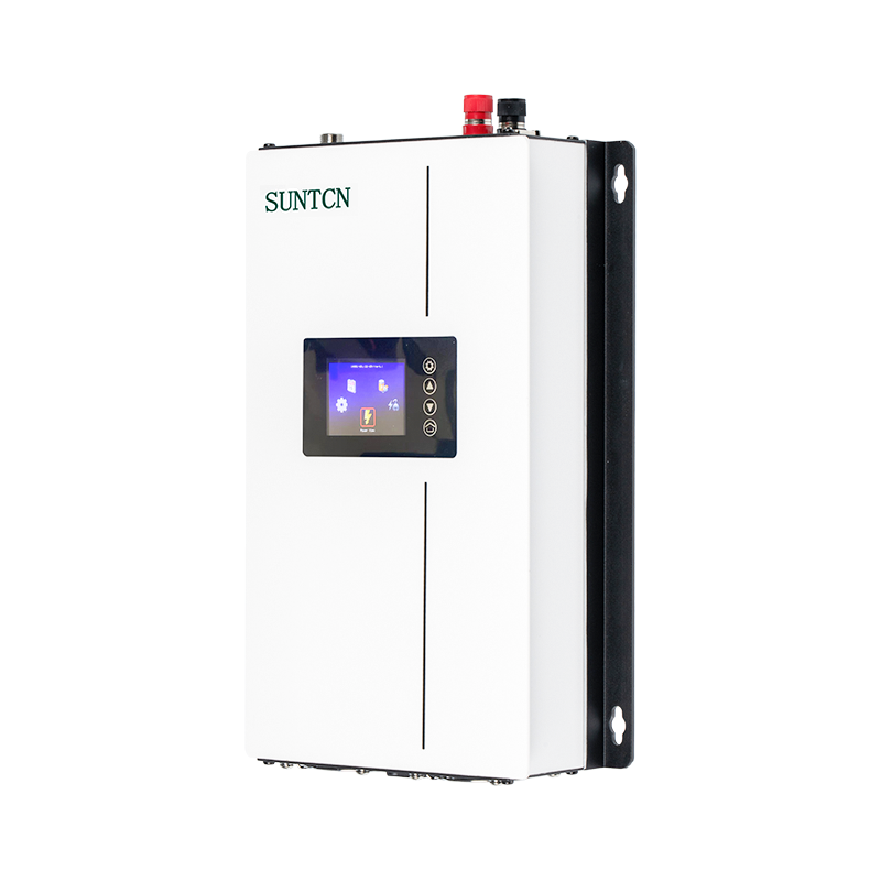
A solar grid tie inverter is the device that makes a rooftop or ground-mounted solar system genuinely useful in a utility-connected setting. Without it, the direct current (DC) electricity generated by solar panels cannot be used by household appliances, fed into a building's electrical system, or exported to the utility grid. The grid tie inverter converts that DC output into alternating current (AC) that is precisely synchronized in frequency, voltage, and phase with the utility supply — enabling seamless integration between your solar generation and the grid. For homeowners, commercial property owners, and solar system installers, understanding how these devices work and what distinguishes a high-quality unit from an average one is foundational to designing a system that performs reliably over its full 10 to 25-year service life.
How a Solar Grid Tie Inverter Works
Solar panels produce DC electricity whose voltage and current vary continuously with sunlight intensity, panel temperature, and shading conditions. A grid tie inverter performs two simultaneous functions: it tracks the maximum power point of the solar array to extract the greatest possible power at any given moment, and it converts that variable DC input into clean, stable AC output that matches the utility grid's electrical characteristics precisely enough to be fed directly into the grid without causing interference or safety hazards.
The maximum power point tracking (MPPT) function is handled by the inverter's control electronics, which continuously sample the panel array's voltage and current and adjust the inverter's input impedance to keep the operating point at the peak of the power curve. This tracking happens hundreds of times per second and is one of the primary factors determining how much energy a system harvests over time, particularly under variable cloud conditions or partial shading. The DC-to-AC conversion itself uses high-frequency switching transistors — typically IGBTs (insulated gate bipolar transistors) or MOSFETs — operating at frequencies of 16 kHz or higher, followed by filtering stages that shape the switched output into a smooth sine wave. The inverter's grid synchronization circuitry continuously monitors the utility voltage and frequency and adjusts the output accordingly, typically maintaining frequency matching within 0.01 Hz of the grid.
Anti-Islanding Protection
One of the most safety-critical functions of a grid tie inverter is anti-islanding protection. If the utility grid loses power due to a fault or scheduled maintenance, the inverter must detect this condition and shut down within milliseconds, stopping all export of solar power to the grid. Without this protection, solar inverters could continue energizing grid conductors that utility workers assume are de-energized, creating a lethal safety hazard. Anti-islanding detection is a mandatory requirement under grid connection standards worldwide — including IEEE 1547 in the United States, VDE-AR-N 4105 in Germany, and AS/NZS 4777 in Australia — and is a non-negotiable feature of any certified grid tie inverter.
Types of Solar Grid Tie Inverters and When to Use Each
Grid tie inverters are available in three principal architectures, each with distinct advantages in terms of system design flexibility, energy harvest performance, cost, and monitoring capability. Choosing the right architecture for a specific installation is one of the most consequential decisions in solar system design.
String Inverters
String inverters are the traditional and most widely deployed grid tie inverter configuration. Multiple solar panels are connected in series to form a "string," and the string's combined DC output is fed into a single inverter that handles the entire array's conversion. String inverters are cost-effective, simple to install and maintain, and available in a wide power range from 1.5 kW for small residential systems to 100 kW or more for commercial installations. Their primary limitation is that the MPPT operates on the string as a whole — if one panel in a string is shaded, soiled, or underperforming, it reduces the output of the entire string, not just itself. String inverters are best suited to arrays installed on a single unobstructed roof plane with consistent orientation and minimal shading throughout the day.
Microinverters
Microinverters are small grid tie inverters installed on — or integrated with — each individual solar panel. Each panel has its own independent MPPT and DC-to-AC conversion, meaning shading or soiling on one panel affects only that panel's output without degrading the rest of the array. This panel-level independence makes microinverters the preferred choice for installations with complex roof geometries, multiple orientations, significant shading from chimneys or trees, or where panels face different compass directions. Microinverters also simplify system expansion — adding panels later requires no consideration of string sizing or inverter input capacity. The tradeoffs are higher upfront cost per watt compared to string inverters and a larger number of electronic units to potentially maintain over the system's life, though modern microinverters are rated for 25-year service lives.
Power Optimizers with a Central String Inverter
DC power optimizers represent a hybrid approach — a small DC-to-DC optimizer module is installed at each panel and performs panel-level MPPT and output conditioning, feeding a regulated DC voltage to a central string inverter that handles the final DC-to-AC conversion. This combines the panel-level performance advantages of microinverters with the efficiency and serviceability of a single central inverter. Power optimizer systems are particularly effective in partially shaded installations where a full microinverter deployment is cost-prohibitive. The central inverter in an optimizer system is the only component requiring installation at mains voltage level, keeping rooftop electrical complexity lower than a full microinverter system.
Key Technical Specifications Explained
Evaluating grid tie inverter specifications requires understanding what each parameter actually means for real-world system performance, rather than simply comparing headline efficiency numbers.
| Specification | Typical Range | What It Governs |
| Peak / CEC Efficiency | 96% – 99% | DC-to-AC conversion efficiency at optimal conditions |
| Weighted (EU / CEC) Efficiency | 94% – 98.5% | Real-world average efficiency across varying load levels |
| MPPT Voltage Range | 200 – 800 V DC | String voltage range within which MPPT operates efficiently |
| Max DC Input Voltage | 600 – 1500 V DC | Maximum open-circuit string voltage permitted at inverter input |
| Number of MPPT Inputs | 1 – 12+ | Number of independently tracked string inputs |
| AC Output Power | 1.5 kW – 100+ kW | Rated continuous AC output at standard conditions |
| Total Harmonic Distortion (THD) | < 3% (typically < 1%) | AC output waveform quality; grid compatibility |
| Nighttime Power Consumption | < 1 W – 5 W | Standby draw when not generating; affects annual yield |
| Operating Temperature Range | -25°C to +60°C | Ambient temperature limits for reliable operation |
| Ingress Protection (IP) Rating | IP65 – IP66 (outdoor); IP20 (indoor) | Resistance to dust and water for installation location |
The distinction between peak efficiency and weighted efficiency is particularly important and frequently misunderstood. Peak efficiency is the conversion rate at the single optimal operating point — typically around 50 to 75% of rated load at ideal DC voltage. Weighted efficiency (CEC in North America, EU weighted in Europe) represents an average across multiple power levels weighted to reflect the actual distribution of operating conditions a grid tie inverter experiences over a typical day and year. An inverter with 98% peak efficiency but poor part-load efficiency may deliver less annual energy than one rated at 97.5% peak but maintaining high efficiency from 10% load upward. Always compare weighted efficiencies when evaluating products for annual yield estimates.
Grid Connection Standards and Certification Requirements
A solar grid tie inverter must carry the appropriate certification for the utility grid it will connect to before any network operator will permit its connection. These certifications verify that the inverter meets the grid's technical requirements for voltage and frequency response, power quality, anti-islanding behavior, and protection relay settings. Installing an uncertified inverter — or one certified to a different grid standard — risks rejection by the utility, denial of export metering, and potential liability if grid faults occur.
- UL 1741 / IEEE 1547 (USA): The primary certification standard for grid interactive inverters in the United States. Newer installations in many states must comply with the SA (Supplemental Agreement) or SB addenda to IEEE 1547, which add requirements for advanced grid support functions including voltage ride-through, frequency response, and reactive power control.
- VDE-AR-N 4105 (Germany): The German low-voltage grid connection standard, which includes strict requirements for reactive power provision, voltage regulation support, and remote shutdown capability via a ripple control receiver — a common requirement for German utility operators managing grid stability in high-PV-penetration areas.
- AS/NZS 4777 (Australia/New Zealand): Sets grid protection and power quality requirements for inverters connecting to Australian distribution networks, including demand response capability requirements for newer installations in networks with high solar penetration levels.
- IEC 62109 / IEC 62116: International standards covering inverter safety and anti-islanding performance that form the basis for certification in many markets outside North America, Europe, and Australia, including large parts of Asia, the Middle East, and Latin America.
Sizing a Grid Tie Inverter for Your Solar Array
Correct inverter sizing is a balance between two competing considerations: ensuring the inverter is large enough to handle the array's expected peak output without clipping, and avoiding oversizing that results in an expensive inverter operating far below its rated capacity for most of the day. The ratio of solar array DC capacity to inverter AC rated capacity — the DC-to-AC ratio, or inverter loading ratio — is the primary sizing parameter, and most system designers target a ratio of 1.1 to 1.3 for locations with moderate peak solar irradiance.
A DC-to-AC ratio above 1.0 means the array's rated output slightly exceeds the inverter's AC capacity — a deliberate design choice based on the fact that solar panels rarely operate at their nameplate capacity simultaneously in real conditions due to temperature derating, soiling losses, and irradiance variability. Operating the inverter at or near its rated capacity for more hours of the day improves overall system efficiency and energy yield, since inverters typically perform better at high load fractions. In high-irradiance locations with excellent panel exposure, ratios above 1.3 risk more frequent clipping — periods where the array could generate more power than the inverter can convert — so the ratio should be kept closer to 1.1 to 1.15 in these cases.
Monitoring, Data Logging, and Smart Features
Modern grid tie inverters incorporate monitoring and communication capabilities that have become standard expectations rather than premium add-ons. These features allow system owners and installers to track energy generation in real time, identify performance issues quickly, and verify that the system is operating as designed throughout its service life.
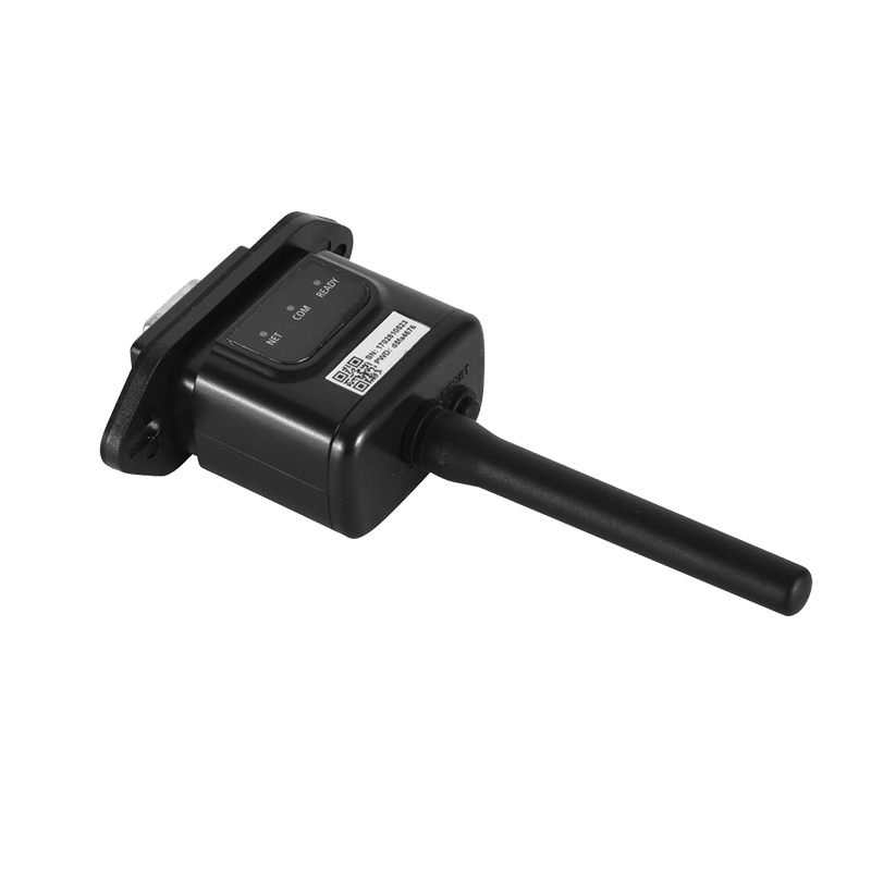
- Wi-Fi and Ethernet connectivity: Most residential and small commercial grid tie inverters now include built-in Wi-Fi or Ethernet communication that connects the inverter to the manufacturer's cloud monitoring platform. Generation data, fault alerts, and performance statistics are accessible via smartphone app or web portal, often with historical data logging and yield forecasting capabilities.
- Modbus RTU/TCP and SunSpec compatibility: Commercial and industrial inverters typically support Modbus communication protocols that allow integration with building management systems, energy management platforms, and third-party monitoring solutions. SunSpec Alliance compatibility ensures interoperability between inverters from different manufacturers within the same monitoring ecosystem.
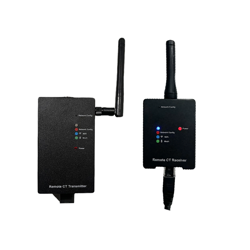
- Export limiting and zero-export mode: Many utilities restrict or prohibit grid export from solar systems, or impose technical limits on maximum export power. Grid tie inverters with integrated CT (current transformer) clamp input can measure the building's import/export power in real time and dynamically throttle their output to prevent export exceeding the permitted level — or to maintain zero export — without curtailing generation that can be consumed on-site.
- Battery storage readiness: An increasing number of grid tie inverter models include hybrid functionality — a DC-coupled battery input that allows a battery storage system to be integrated alongside the solar array. Hybrid grid tie inverters manage the charge and discharge of the battery relative to solar generation, household consumption, grid tariff schedules, and time-of-use optimization, making them the foundation of a fully integrated solar-plus-storage system.
Installation and Maintenance Considerations
A correctly specified grid tie inverter installed in adverse conditions — excessive heat, poor ventilation, direct rain exposure on a non-weatherproof unit, or inadequate cable sizing — will underperform and may fail prematurely. Installation environment and ongoing maintenance practices are as important as equipment selection in determining long-term system reliability.
- Thermal management and location: Grid tie inverters derate their output at elevated ambient temperatures to protect internal components — a process called thermal derating. For every degree above approximately 45 to 50°C (depending on the model), output capacity is reduced by a fraction of a percent. Installing the inverter in a shaded, north-facing location (in the southern hemisphere) or inside a ventilated equipment room minimizes thermal derating and maximizes annual energy yield. Avoid south-facing wall installations in full sun, particularly in hot climates, where afternoon ambient temperatures can reduce inverter output by 10 to 20% during the peak generation hours of the day.
- DC cable sizing and voltage drop: Undersized DC cables between the solar array and the inverter cause resistive losses that reduce energy harvest and generate heat in the cable insulation, creating a fire risk over time. Size DC cables to limit voltage drop to below 1% at maximum string current, and use UV-stabilized, double-insulated solar cable rated for DC applications rather than general-purpose AC building wire.
- Periodic inspection and firmware updates: Grid tie inverters require minimal routine maintenance, but annual inspection of DC and AC terminal connections for signs of corrosion or loosening, verification of the inverter's fault log for recurring errors, and application of manufacturer firmware updates — which often improve grid compliance, MPPT performance, or monitoring features — are worthwhile practices that protect the investment over the system's full service life.
A solar grid tie inverter is the most technically complex and performance-critical component in any grid-connected solar system. Selecting the right type and capacity for the array configuration and site conditions, verifying certification for the applicable grid standard, and ensuring correct installation and monitoring setup are the steps that separate a solar system delivering its full financial and environmental return from one that quietly underperforms for years without anyone noticing.